Why bother? You will become angry, frustrated, dirty, cold and it’ll give you tourettes, hopefully this guide will ease the pain if you are thinking of doing a conversion. There is a lot of information on the internet regarding megasquirt - but not a lot related to an 8v Gti Golf! Take your time, concentrate on one thing at a time and your head shouldn't explode. The following is related to the ups and downs I had when installing it.
The Mk2 Volkswagen Golf Gti is perhaps one of the easiest cars to convert to megasquirt, most of the hardware is already there. The digifant fuel system is full electronic injection so requires no modification and most of the wiring is already there, you just need a loom from ms to stock ecu and from ms to the new sensors. If your car is a mechanical injection or carb model it is probably easier to fit the entire injection system from a digifant car - why spend a weekend fabricating a fuel rail when you can buy one for pennies?
A WORD OF WARNING Please take care when working on fuel systems, your mum warned you about playing with matches for a reason! Before you start making looms and ripping your car to bits read the Megamanual and try to understand some of it. A lot of the information is not relevant to a Golf install, pay attention to stuff on hall senders, soldering, sensor outputs and anything else you don’t have a clue about. Also read the forums on Clubgti , megavag and vwvortex. I've been working with cars for 15 years and understand Bhp and RPM. Put a PC in front of me and suddenly I'm an apprentice again, I don’t understand Gb or RAM. Eliot fortunately does. He soldered my ECU, offered lots of advice, some of which I chose to ignore and generally moaned a lot. Top chap.
NEW WIRING LOOM
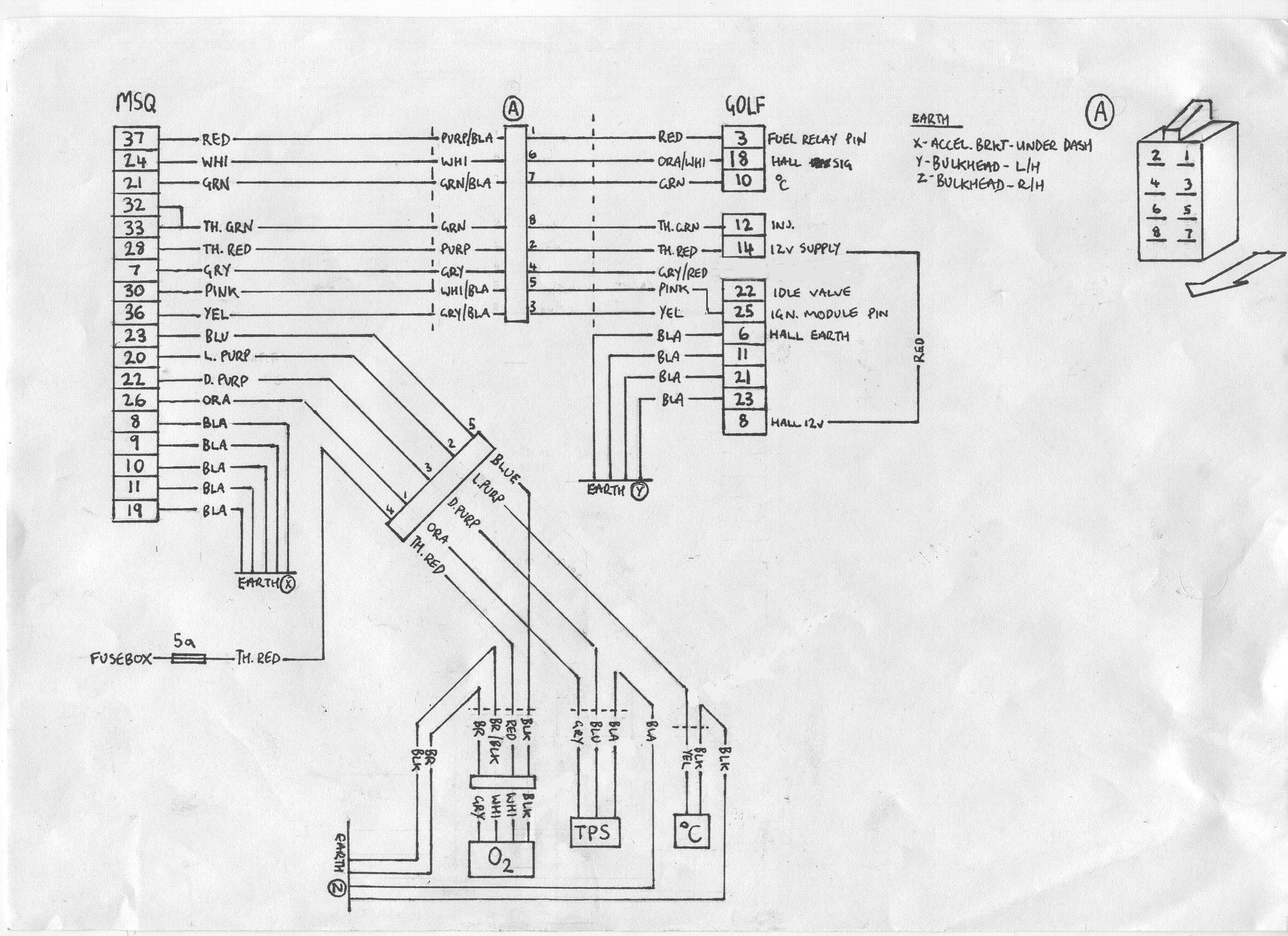
I managed to get hold of a genuine Volkswagen wiring manual, which was worth its weight in gold when it came to making a wiring loom, particularly useful for ecu pin outputs, earth points and tracing random wires. There are a hundred different ways of fitting Megasquirt, I decided to do a ‘plug and play’ install, which could be swapped from the standard digifant system to megasquirt as easily as possible, this was to prove very useful during initial tuning - this was my only car and I couldn't walk the 20 miles to work every day. You could choose to make an entirely new loom for your conversion and ditch the stock wiring loom. Do your research – I spent hours on my design. When I converted my Golf the V3 board had just been released so I used one of these running mega squirt and spark extra. I would advise using the latest Beta software availabe as it tends to have more features and less bugs. You have too many options to list here but you may wish to run fuel only, without a TPS (mapdot mode), remove the ignition module (MS has this internally) or even convert to a Ford EDIS system, it is your choice but this guide is a simple, easy and reliable method of installing MS.
WHAT TO DO IN THE KITCHEN WHEN YOUR MISSUS IS AWAY
String templates are handy for getting the wire lengths right and fit the loom in the car during assembly to make sure it's ok. Make your life easier by using different coloured wires and decent connectors - follow the guides on the MS site! The stock Digifant ECU has most of the inputs and outputs required so a spare ECU was gutted, this now only serves as a connector between the stock engine sensors, injectors etc and the Megasquirt ECU. The extra sensors needed are a throttle position sensor (TPS) , air intake temperature (IAT) and a lambda probe (O2). I decided to place the MS inside the car to keep it nice and dry and although space is limited it will fit in the undertray without fouling on the accelerator pedal linkage. Other popular locations are in the glovebox or near the stock ECU (just make sure it can't get wet)
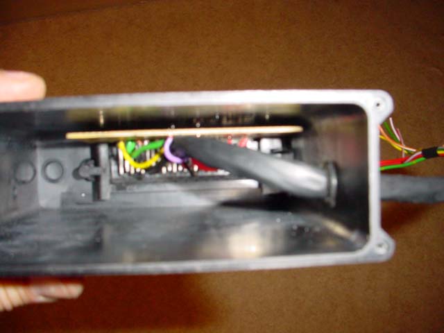
GUTTED STOCK ECU
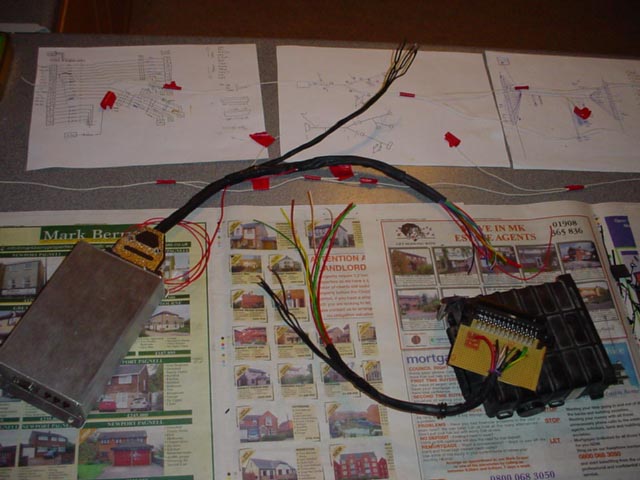
Spend time making sure your loom is as weather tight as possible, there are no awkward bends which may fail and no risk of it chafing against something sharp. The engine bay is a harsh environment for electrics – if you mess it up you will need that RAC membership or even worse a fire extinguisher... I did want to use a bulkhead wiring plug where the loom enters the car but these were too costly. In the end I used a din plug (like the one on the back of your car stereo) and waterproofed it with a small plastic bag. Not ideal but no failures so far….
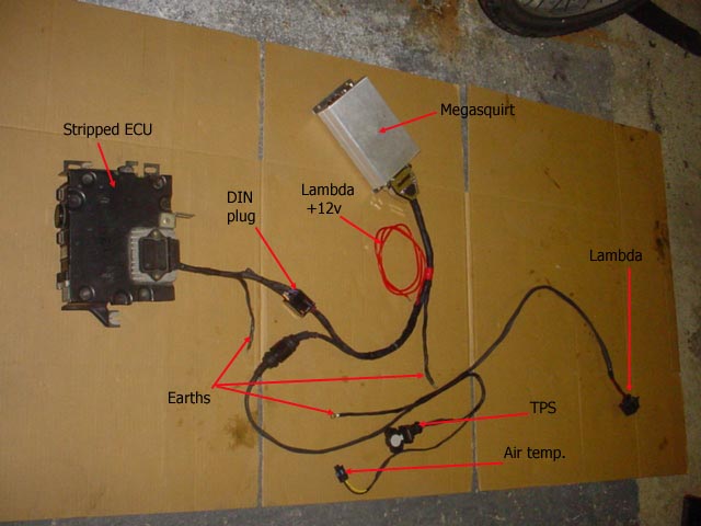
FINISHED LOOM
While you are busy thinking about which version of MS to use and how to design a wiring loom, you need to think about the extra sensors MS needs. I had read an Audi 80 auto throttle body would fit which has a TPS (it fits 16v KR engines). My local VW breakers had one which has a TPS and the 2 micro switches used on the standard digifant set up – ideal for my ‘plug and play’ install. Unfortunately when I tried it on the car it fouled on the fuel rail which meant I could change my fuel rail or throw it in the bin. As I wanted to keep as much of the engine standard as possible I ended up retro fitting a sensor onto the standard throttle body. The body required a little modification before a bracket was designed to fit (ideally in steel, not aluminium).The TPS I used was from a Rover 1.8 ‘K’ series engine and has a ‘D’ shaped hole which fits the VW unit nicely.
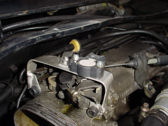
TPS BRACKET
The O2 sensor was a REAL pain in the exhaust. It has to be fitted as close to the manifold as possible and preferably where all 4 cylinders join. It must NOT point down as it will collect moisture and fail, keep it above 3 o'clock. The front pipe is tricky to remove – I ended up dropping the subframe to get it out and spent many fun hours on my back in the driveway - is there an easy way to remove it? A threaded boss was then welded to it. There is not much room in the tunnel, with hindsight I would have fitted it pointing backwards at 45’. If you can, weld it with the pipe in situ, screw in the sensor and run the loom up to the engine bay. A narrowband sensor was fitted initially to keep it simple and cheap.
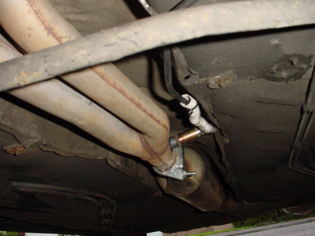
O2 SENSOR
The air intake temperature sensor (IAT) fits nicely in the rubber intake pipe. Just hack a hole in it and push it in making sure it is well sealed to avoid air leaks. Alternatively you could drill and tap a hole in the manifold (although you may have heat soak problems) I used the recommended GM sensor AX1 (already configured for MS) and pigtail connector available from Woolfe Racing.
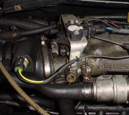
IAT AND TPS
Depending on how you design and route your loom you may need an extra hole in the bulkhead to run some wires. I put a hole next to the speedo drive (direct and quite weather tight) If you got the lengths on your wiring loom correct you should be able to fit it easily, connect it up and your car is almost ready to fire up.
Other stuff
You will need to supply a vacuum signal to the Megasquirt, I simply fitted a t piece to the MFA vacuum pipe under the dash and ran this to the ECU. If your car does not have an MFA display you may need to run a pipe from the engine, the length of the pipe is not important.
The digifant system takes its distributor signal at 6 deg before TDC. This is not enough for megasquirt. I was hoping it would go into next cylinder mode but it seems MS is only capable of receiving a spark signal 270 deg out of 360. 6 deg falls into the area it cannot read from so the distributor needs to be moved – so much for ‘plug and play’!
You will need to change the coolant sensor or use Easytherm to modify the values. I soldered a new ‘sperm’ in a spare sensor – available from RS components, then removed the black sensor used for the dash gauge and fitted it there, allowing easy changes from the standard sensor to the MS one although I now had no temperature gauge in the car.

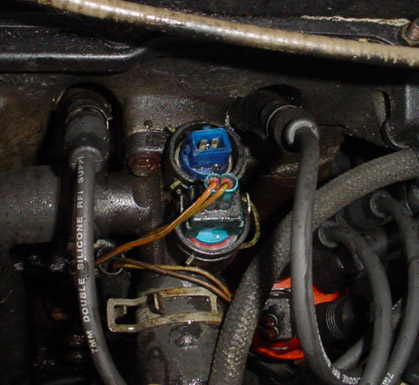
TIMING MARKS & COOLANT TEMP. SENSORS
Thats the conversion pretty much complete. I thought at this point that the car would try and fire up and spent some time scratching my head on cold evenings with it cranking over but not firing. The problem turned out to be a poor voltage differential from the hall sensor, ideally it should go from 0v to 12v when spinning the distributor. With MS installed it changed from 10v to 12v - not enough. This was cured by fitting a pullup resistor between the 12v supply and the hall signal wire. I used a 1k resistor which worked fine, pulling it to around 4v. I did not have to use the hall schematics shown in the megamanual.
The idle screw may also need to be adjusted once the engine is running.
I had also managed to keep costs down by 'borrowing' wiring parts from work, brains from friends and patience from the missus, total cost - under Ł200!.
Please note: some Gti’s will have different wiring layout, not all cars will work with this exact setup. If you are not confident in making your wiring loom or soldering your ECU together there are companies that will do it for you - check the 'official suppliers' on the MS site.
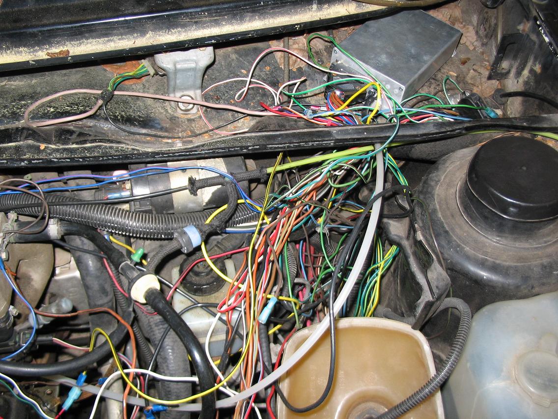
If your install looks something like this please, for the love of God, take up another hobby.
Digifant ECU pin out
| 1 | |
| 2 | O2 earth |
| 3 | Fuel relay (pin85) |
| 4 | Knock sensor |
| 5 | Knock sensor |
| 6 | Throttle switch |
| 7 | Knock sensor |
| 8 | Hall sender |
| 9 | Air temp (pin1) |
| 10 | Coolant sensor |
| 11 | Throttle switch |
| 13 | |
| 14 | Idle valve 12v |
| 16 | Connector behind dash |
| 17 | Air flow meter |
| 18 | Hall sender |
| 19 | Earth |
| 21 | Air flow meter |
| 22 | Idle valve |
| 23 | Idle valve |
| 25 | TCI control unit |